A few days ago, I was fiddling with my teensy 3.1 and an ADS 1115 ADC converter to measure a battery voltage... And I was wondering what I could do with the other ADCs of the 1115. I came up with power measurement. So I quickly added a shunt sized to keep the voltage drop below a fifth of a volt at the expected system power consumption. Why 200mV? Because it won’t affect my circuit, and using the ADS1115 programmable gain amplifier I can get close to it’s full range, leaving a 25% headroom. I know my measurements will always fall in a certain range so I can go close to the ADC max range, but If I want to extend the range I can lower the shunt resistor at the expense of precision. This gave me reasonably accurate measurement at around 100ma using a 1.5 ohm shunt.
Sizing the Shunt
First, determine the max voltage drop you can afford, remember that this drop will result in heat.
Ex. A 1V drop at 1A is 1W of heat that your shunt will dissipate and you will need to choose your shunt resistor according to your power dissipation.
So for my 100mA@5V circuit
Determine Shunt size
R = E/I : R = 0.2V / 0.1 = 2ohm
Calculate the power dissipated by your shunt
P=EI : P = 0.2 * 0.1 = 0.02W
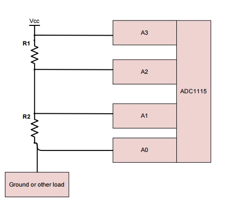
To measure the power, I setup the ADC as a dual channel differential and then hooked it up to the shunt and load in the following manner :
Having succeeded with a relatively big load, I wondered how little of a current could be measurable. So I assembled a test bed and hooked a 1Mohm resistor in series with a 25K shunt. I selected a 25K shunt because I had one lying around and the voltage drop would be measurable...According to my calculation the drop would be around 50mV. The expected current for this test circuit was around 2uA (I=2V/1000000ohm).
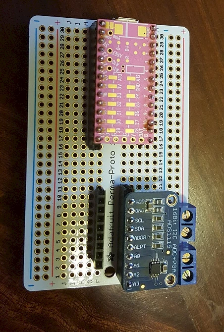
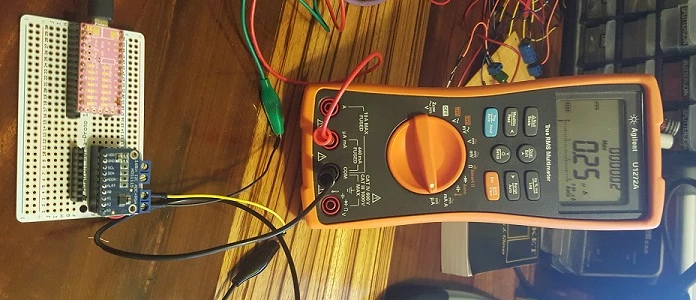
When I powered it up I was getting weird results that, besides being weird, were all over the place. At first, I looked at the code and played around with the ADC params, sampling rate and Gain, but to no avail. I then probed the circuit with my digital multimeter (DMM) and, sure enough, the voltage was not stable at the ADC inputs. I wondered how much current this ADC consumes while measuring, I probed and, sure enough, I was getting peaks of 0.25uA.
I then realized that I was disturbing the circuit with my measurements. What’s needed is a way to have an high impedance amplifier that can buffer the voltage for the ADC to read. Say hello to the unity gain buffer amplifier. A simple opamp circuit with it’s negative feedback hooked to it’s output and it’s positive feedback connected to the souce we want to buffer. To test this I configured an LM324 I had lying around as four voltage follower and then proceeded to create a proto board with the following setup. It worked!
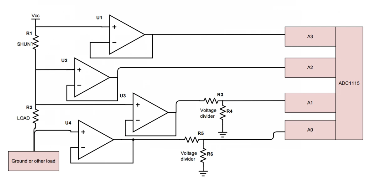
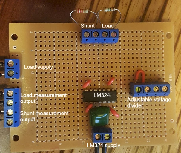
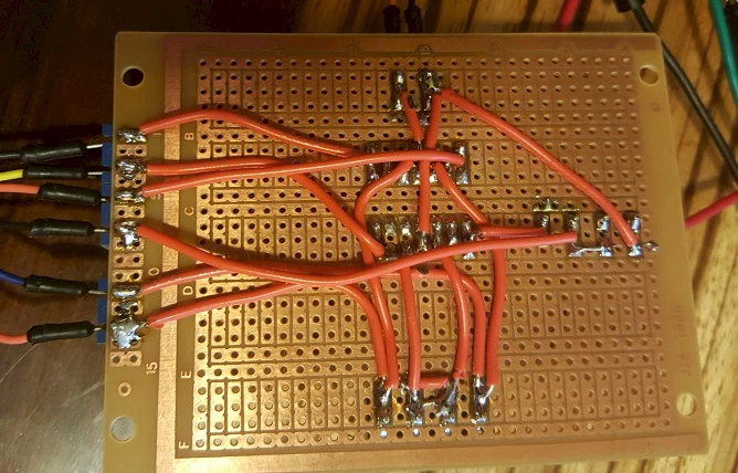
The more astute reader will find it’s missing a voltage divider, it’s omitted here because I expected to only test with the load going directly to ground after.
The readings I was getting were now in line with what was previously calculated

2.07uA@1.959V….Let’s confirm the voltage drop on the load by attaching the DMM to it.
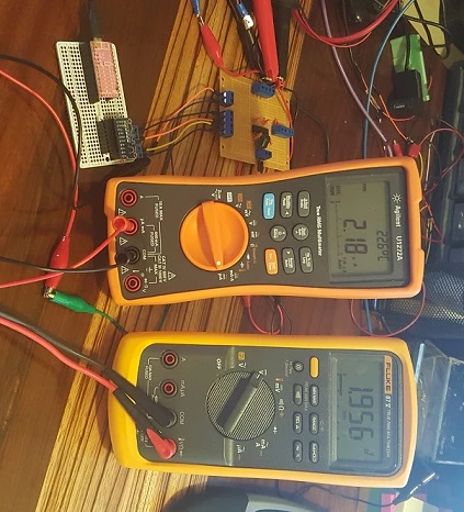
Hum, the readings on my DMMs are a bit off, but so are the ones from the ADC now...

Is it possible that the impedance of the voltmeter is messing with my readings? Let’s unplug the voltmeter and see what will happen.
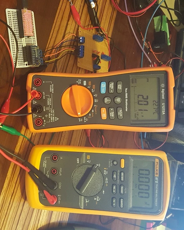
Yep, having the multimeter in parallel with the load decreased it’s overall resistance and introduced errors in the measurement…
Maybe we can use this info to calculate the 87V internal resistance. Using only the data collected from our ADC, let’s keep the precision DMM out of the equation.
So we were up to 2.25uA from 2.07uA…
At 2.25uA@1.956V Our apparent circuit resistance is 869333ohm.
At 2.01uA@1.959V Our resistance is 946376ohm.
So what parallel resistance did the fluke add to our initial measurement?
R = (946376 * 869333)/(946376-869333) = 10678605ohm. Is this accurate? Let’s confirm by measuring the internal resistance of the 87V
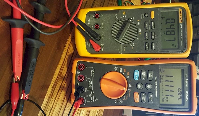
Not to bad, I have to say...An error of 432Kohm (sound like a lot this way)...Or about 3.9% (sounds better this way ) which is quite good considering the low power we are playing with.
What’s next
I want to measure really really small current, just for the fun of it… I have no practical use for measurement beyond the precision of my multimeter's capabilities. Except for the fun of experimenting and saying that I’ve done it myself. So I will now shop for high value resistances to use as dummy “load”...(can we really call that a load when you get in gigaohm territory?). The LM324 opamp is not suited for this kind of application with it’s input bias current of 20nA and 2-3mV input bias. We can easily find some with 2fA bias current and 1mV input bias, these should be more suited for this kind of application. I will also check to add some gain to the op-amp, but only if it doesn’t introduce more errors. Adding gain means the shunt resistor can be lowered. As it stand right now, no parts of the circuit are protected, so maybe add some protection here and there.

