
Making non-manifold models unrepresentable

3D printing and mechanical simulations are two situations which require solid modelling, that is, a representation of 3D objects which clearly distinguishes the parts of an objects which are filled with solid material and the parts which are filled with air. They are also two domains in which one of our well-known clients, Autodesk, is heavily involved.
Solid modelling and surface modelling both represent 3D objects via their surfaces, but solid modelling has the extra requirement that the surfaces must be "manifold", also known as "closed" or "watertight". Shapeways has a friendly introduction to the topic, with simple examples which we will use below.
As developers of custom software, we know how much effort is spent tracking down bugs, and we use a variety of techniques to avoid them, such as thorough validation by our QA team and test-driven-development. My favorite technique is to choose a programming language in which entire categories of bugs, such as null-pointer exceptions, are eliminated. Of course, there is more to bugs than just crashes and unexpected exceptions: what about semantic bugs, where the program ends up in a state which is legal according to the language, but invalid according to the semantics of the program? This is precisely the situation we face with solid modelling: any collection of faces is a valid value of type List
In this article, I present a technique to make non-manifold models unrepresentable, thereby eliminating an entire category of semantic bugs caused by transformations which break the watertightness invariant.
Linear types
I must admit that I haven't implemented the technique I am proposing. The main reason is that my technique relies on so-called "linear types", a programming language feature which isn't very complicated, but which very few languages support. One language in this list is Rust, which seems to be growing in popularity, so there is hope!
Anyway, linear types are very simple to explain: once a linear value is assigned to a variable, this variable must be used exactly once before going out of scope. For example, in the following snippet, only y is linear.
{
  x := fetchValue(defautValue()); // linearity violation: x is used twice
  y := fetchValue(x);
  z := fetchValue(x); // linearity violation: z is used zero times
  return y;
}
Since y is the only variable which is used in a linear fashion, if fetchValue's return type was linear, this snippet would raise two linearity-check errors.
Two-manifolds
As explained in the Shapeways article, a 2-manifold surface is one in which each edge is connected to exactly two faces. In BRep-speak, each edge consists of two coedges, and each coedge is used by exactly one face.
In order to guarantee this property, current implementations of solid modelling typically use the following technique. First, a surface is constructed by creating a variety of objects: vertices, edges between those vertices, coedge objects wrapping those edges, loops consisting of a circular linked list of coedges, faces filling in the loops, shells enclosing a volume via several faces, and finally lumps, consisting of an outer shell and several hollowed-out shells inside of it. Next, this network of objects is checked for validity, and a runtime error is raised if, for example, the same edge is used more than twice.
This validation step is good if it catches errors during the development, but it is of little help after the product has shipped, when corner cases are discovered and user manipulations result in unhandled exceptions or rejected manipulations. It would be much better to make sure that all the manipulations are implemented in a way which always maintains watertightness, even in corner-case situations which have not been tested. Such guarantees are what static tests provided by the language are all about.
Linear CoEdges
In order to statically-guarantee that only two-manifolds can be produced, I suggest a different API whereby CoEdge would be a linear type. Also, the two coedges representing the two sides of the same edge would be produced at the same time, thereby requiring that both linear variables be used as part of a face before going out of scope.
By making the faces linear themselves, we ensure that each face must be used as part of a shell before going out of scope. Finally, by making the shell itself linear, we ensure that only one shell will be created, and subsequently returned, as the API would not provide any other way for shells to be consumed.
Together, those rules ensure that the resulting shell will be a valid two-manifold, as all of its faces will be constructed exclusively from edges which are connected to exactly two of the shell's faces.
Examples
In order to make my scheme more concrete, let's go over all the examples of non-manifold objects from the Shapeways article and verify that those objects would be rejected at compile-time. To do this, I'll use an imaginary language supporting linear types, tuples, and a few other auxiliary structures. I will use this language to construct coedges, faces, and shells. For simplicity, the code is only specifying the topology of the objects (which parts are connected to which), not its geometry (where in space do all the vertices lie).
The important part about those snippets is that when they construct invalid non-manifold objects, they fail the linearity check, and when they construct valid objects, they pass the check.
Holes
The first example of a non-manifold object given by Shapeways is a cube minus its front face. I have labelled all the coedges with two letters according to the following scheme: "DB" means "the coedge of the Downwards face which is located towards the Back".
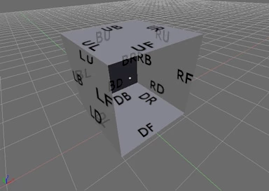
It is easy to see that this object is not watertight, and it's also easy to see why my scheme would reject such an object: the coedges UF, RF, DF and LF do not have a matching coedge, and so the variables corresponding to the missing coedges will fail the linearity test.
Shell createOpenCube() {
  (bu, ub) := createCoEdges();
  (br, rb) := createCoEdges();
  (bd, db) := createCoEdges();
  (bl, lb) := createCoEdges();
  back := createFace(Loop {bu, br, bd, bl});

  (uf, fu) := createCoEdges(); // linearity violation: fu is used zero times
  (ul, lu) := createCoEdges();
  (ur, ru) := createCoEdges();
  up := createFace(Loop {uf, ul, ub, ur});

  (rf, fr) := createCoEdges(); // linearity violation: fr is used zero times
  (rd, dr) := createCoEdges();
  right := createFace(Loop {rf, rd, rb, ru});

  (df, fd) := createCoEdges(); // linearity violation: fd is used zero times
  (dl, ld) := createCoEdges();
  down := createFace(Loop {df, dl, db, dr});

  (lf, fl) := createCoEdges(); // linearity violation: fl is used zero times
  left := createFace(Loop {lf, ld, lb, lu});

  return createShell(Set {back, up, right, down, left});
}
Coincident edges
The next example looks watertight, but in fact there is a crack between the coedges UFL-UFR and the coedge FU. The the video in the corresponding section of the Shapeways article makes the crack very clear.
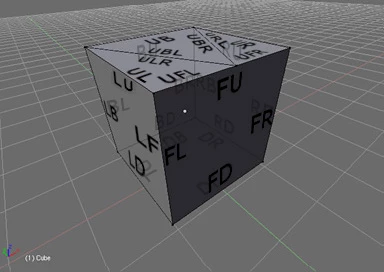
Once again, those coedges are missing a matching coedge, and the missing coedges fail the linearity check. I have highlighted the part of the code which differs from the previous snippet.
Shell createCubeWithZigZag() {
  (bu, ub) := createCoEdges();
  (br, rb) := createCoEdges();
  (bd, db) := createCoEdges();
  (bl, lb) := createCoEdges();
  back := createFace(Loop {bu, br, bd, bl});

  (ubr, url) := createCoEdges();
  (ubl, ulr) := createCoEdges();
  upBack := createFace(Loop {ub, ubr, ubl});

  (ur, ru) := createCoEdges();
  (ufr, fur) := createCoEdges(); // linearity violation: fur is used zero times
  upRight := createFace(Loop {ur, ufr, url});

  (ul, lu) := createCoEdges();
  (ufl, ful) := createCoEdges(); // linearity violation: ful is used zero times
  upLeft := createFace(Loop {ul, ulr, ufl});

  (rf, fr) := createCoEdges();
  (rd, dr) := createCoEdges();
  right := createFace(Loop {rf, rd, rb, ru});

  (df, fd) := createCoEdges();
  (dl, ld) := createCoEdges();
  down := createFace(Loop {df, dl, db, dr});

  (lf, fl) := createCoEdges();
  left := createFace(Loop {lf, ld, lb, lu});

  (fu, uf) := createCoEdges(); // linearity violation: uf is used zero times
  front := createFace(Loop {fu, fr, fd, fl});

  return createShell(Set {back, upBack, upRight, upLeft, right, down, left, front});
}
Internal faces
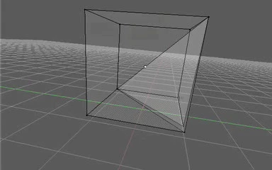
Next, a different kind of manifold violation: instead of missing a face, this version has an extra face where it shouldn't: inside the object.
It's not so much the fact that the face is inside the object which is problematic, it's the fact that the face is sharing edges which are already used twice by the outside faces. Since createCoEdges() only creates two coedges at a time, this means that a second call to createCoEdges() will be needed in order to create the third copy, along with a fourth copy which will end up being unused and will thus fail the linearity check.
Shell createCubeWithInternalFace() {
  ...
  (dfm, dbm) := createCoEdges();
  ...
  (md, md2) := createCoEdges(); // linearity violation: md2 is used zero times
  ...
}
But then, what if a second copy of the internal face was created in order to use up all those trailing variables? Wouldn't that pass the linearity check even though using an edge four times is forbidden? Well, yes, such an object would pass the linearity check, but it wouldn't be fair to describe this as "using the same edge four times". Instead, each call to createCoEdges() would denote a separate edge, whose geometry happens to coincide with that of another edge. This is a common occurence in boundary representations, and is totally fine.
What isn't fine about a shell consisting of a cube plus two connected internal faces is that the two internal faces are not connected to the rest of the shell. This is a class of bugs which isn't covered by this version of my scheme.
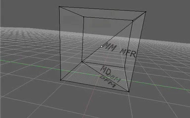
Interestingly, if we rearrange the coedges so that the two Downward triangles connect with the two internal Middle triangles instead of with each other, we obtain a valid, connected object! This distinction would not have been possible if the faces were defined by the geometry of their edges instead of by the topology of their coedges.
Here is the code for constructing such an object, which would look just like the one in the above picture, except the gap between the two internal faces would be infinitely-small.
Shell createCubeWithKnifeCut() {
  (mm1, mm2) := createCoEdges();
  (mfr1, fr) := createCoEdges();
  (md1, dfm) := createCoEdges();
  innerFace1 := createFace(Loop {mm1, mfr1, md1});

  (mfr2, rf) := createCoEdges();
  (md2, dbm) := createCoEdges();
  innerFace2 := createFace(Loop {mm2, mfr2, md2});

  (bu, ub) := createCoEdges();
  (br, rb) := createCoEdges();
  (bd, db) := createCoEdges();
  (bl, lb) := createCoEdges();
  back := createFace(Loop {bu, br, bd, bl});

  (uf, fu) := createCoEdges();
  (ul, lu) := createCoEdges();
  (ur, ru) := createCoEdges();
  up := createFace(Loop {uf, ul, ub, ur});

  (rd, dr) := createCoEdges();
  right := createFace(Loop {rf, rd, rb, ru});

  (df, fd) := createCoEdges();
  downBack := createFace(Loop {dbm, db, dr});

  (dl, ld) := createCoEdges();
  downFront := createFace(Loop {df, dl, dfm});

  (lf, fl) := createCoEdges();
  left := createFace(Loop {lf, ld, lb, lu});

  front := createFace(Loop {fu, fr, fd, fl});

  return createShell(Set {innerFace1, innerFace2, back, up, right, downBack, downFront, left, front});
}
Overlapping faces
The last case is mostly a duplicate of the previous one: the front edge of the top face is used by three faces, so two calls to createCoEdges() are necessary.
Connectedness etc.
Before leaving, a few caveats about the technique.
First, this technique is an example of a pessimistic check: if a piece of code passes the check, then we accept the code because we know that it will always produces correct two-manifolds, whereas if a piece of code fails the check, we reject it because we don't know whether it is correct or not. So even if you are one of the lucky few who are using a language which supports linear types, you might decide that you are sufficiently confident in the correctness of your current code, and that the cost of reimplementing all of your transformations to make them pass the check would outweigh the improved correctness guarantee. And given the size of the codebase of a typical solid modelling package, that's probably a wise decision! On the other hand, if you're about to start a new green field project in the world of solid modelling, you might want to consider a language which supports linear types, and use this technique to eliminate an entire class of bugs for the lifetime of your product.
Second, in order for a boundary representation to be valid, it is not sufficient for all the shells to be two-manifolds. For example, a spherical shell indicating a hollow hole inside a larger spherical shell is valid, but if the inner sphere is moved so that it intersects with the outer sphere, the representation becomes invalid. I have a hard time imagining how such a property could be verified at compile time. Other properties, such as connectedness, do seem achievable, via something like property-preserving transformations. If this post generates enough interest, I might write a follow-up describing such a variant.